

Article Summary: A Through Core Current Transformer provides a practical way to measure AC current and support circuit protection without directly connecting measurement instruments to high-current conductors. Anqiang Power develops the LMZC-10 series for power distribution applications, including medium-voltage switchgear, metering panels, RMU, GIS, compact substations, and industrial power systems. With a toroidal silicon steel core, copper secondary winding, epoxy resin insulation, and compact construction, this transformer is designed for stable current sampling and reliable long-term operation.
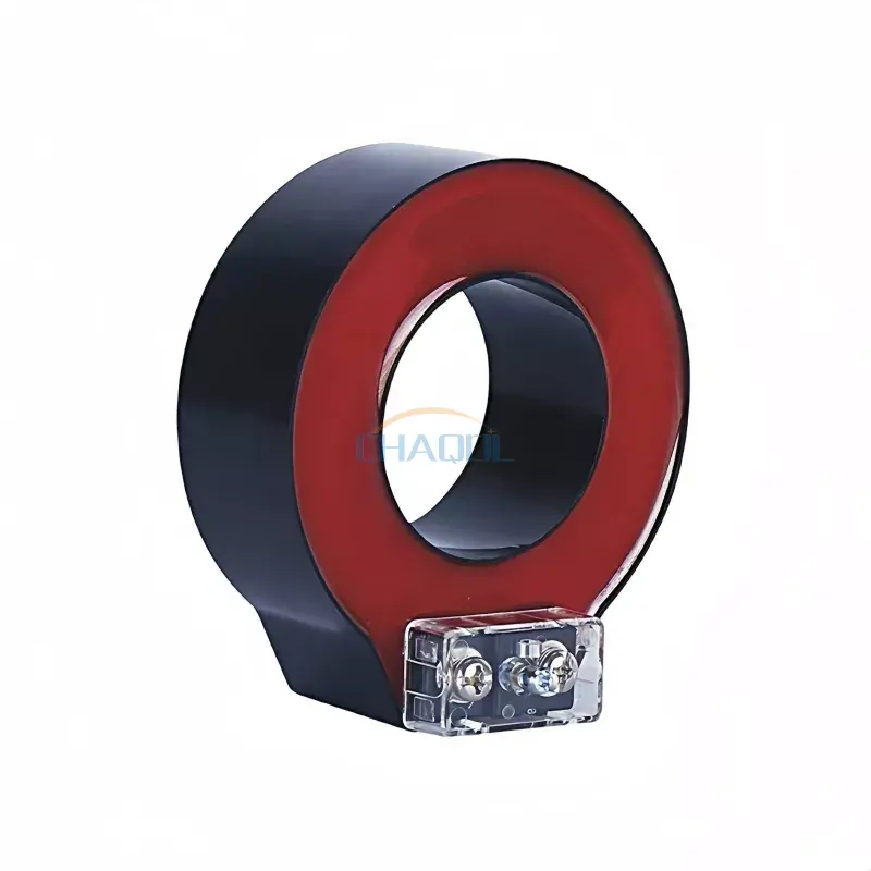
Table of Contents
- What Is a Through Core Current Transformer?
- How Does a Through Core Current Transformer Work?
- What Is the Structural Design?
- Which Technical Parameters Matter Most?
- Where Is a Through Core Current Transformer Used?
- What Are the Main Performance Advantages?
- How Should You Select the Right Model?
- What Installation Practices Should Be Followed?
- Frequently Asked Questions
- Conclusion
What Is a Through Core Current Transformer?
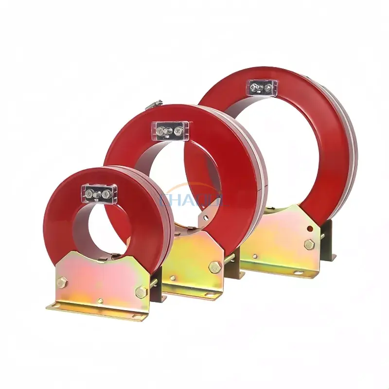
A Through Core Current Transformer is an electrical instrument transformer designed to convert a high primary current into a lower, standardized secondary current that can be safely used by measuring instruments, meters, and protection relays. Instead of connecting the measurement circuit directly to the high-current conductor, the primary cable or busbar passes through the transformer's core.
The LMZC-10 series from Anqiang Power is designed for AC power systems with operating voltages below 35kV. It can be configured for applications involving voltage levels such as 10kV, 24kV, and 35kV according to project requirements. Its structure is suitable for applications where dependable current sampling, metering, and relay protection are essential.
Unlike a conventional transformer that may have a dedicated primary winding, a through-core design uses the conductor passing through the core as the primary turn. This construction can provide a compact solution for electrical distribution equipment while simplifying integration into suitable systems.
How Does a Through Core Current Transformer Work?
The operating principle is based on electromagnetic induction. When alternating current flows through the primary conductor, it generates a magnetic field around the conductor. The magnetic flux passes through the transformer's core and induces a proportional current in the secondary winding.
The resulting secondary current is typically standardized for connection to measurement or protection equipment. For the LMZC-10, secondary current options include 5A and 1A, depending on the selected configuration.
The basic operating process can be summarized as follows:
- The primary cable or busbar carries the system current.
- The primary conductor passes through the magnetic core.
- Alternating current creates magnetic flux within the core.
- The secondary winding responds to the magnetic flux.
- A reduced secondary current is delivered to the measuring or protection circuit.
- Connected equipment uses the signal for monitoring, metering, or protective functions.
This arrangement separates the measurement circuit from the primary power conductor, making current monitoring more practical in many distribution applications.
What Is the Structural Design?
Transformer construction has a direct influence on measurement stability, insulation performance, environmental resistance, and service life. The LMZC-10 uses a toroidal silicon steel core combined with epoxy resin casting insulation.
Core and Magnetic Circuit
The toroidal silicon steel core provides the magnetic path required for electromagnetic induction. A properly designed magnetic circuit helps maintain stable current transformation characteristics and supports reliable measurement performance.
Primary Conductor
The primary conductor passing through the core functions as a single-turn primary winding. This arrangement allows the transformer to measure the current flowing through an existing cable or busbar without requiring a conventional multi-turn primary winding.
Secondary Winding
The secondary winding uses high-conductivity copper wire to produce a stable output current for connected meters and protection devices. The secondary circuit must be correctly connected and handled according to the equipment design and applicable electrical safety procedures.
Insulation and Housing
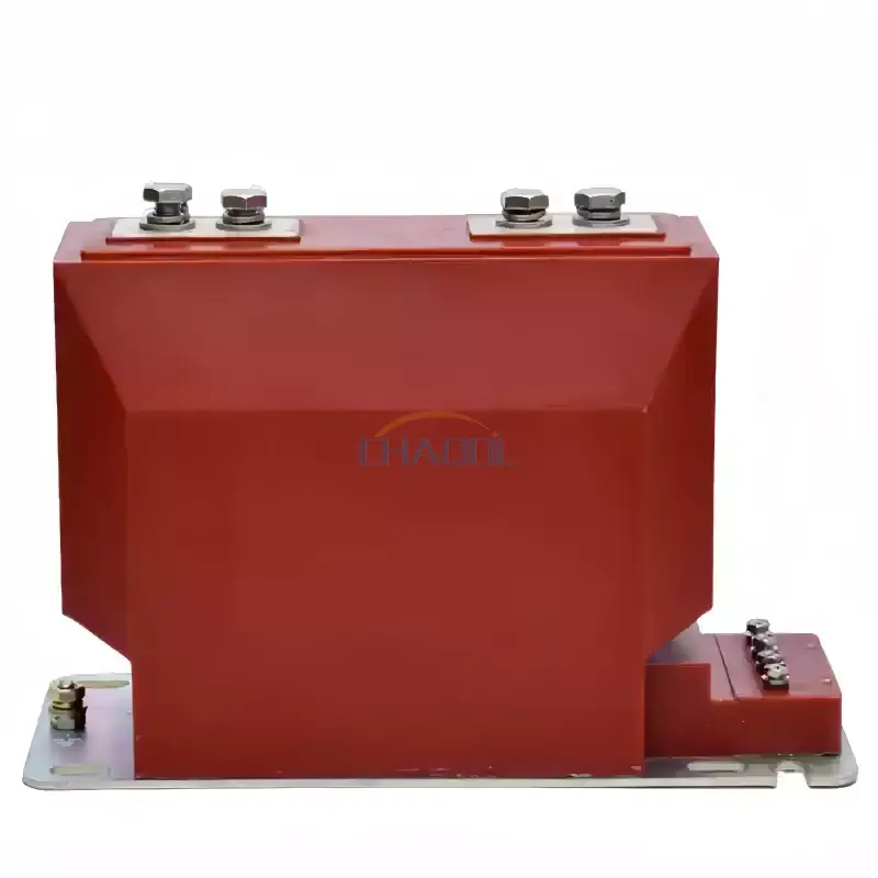
The product uses epoxy resin insulation and a flame-retardant ABS housing. A sealed transparent terminal cover is also designed to improve visibility around the connection area while supporting safer wiring and maintenance work.
Which Technical Parameters Matter Most?
Choosing a current transformer requires more than simply matching the nominal current. Engineers should evaluate the electrical system, measurement purpose, installation dimensions, accuracy requirements, and protection requirements together.
| Parameter | LMZC-10 Reference | Why It Matters |
|---|---|---|
| Product model | LMZC-10 | Identifies the applicable product configuration |
| Rated frequency | 50/60Hz | Matches common AC power-system frequencies |
| Secondary current | 1A / 5A | Determines compatibility with connected equipment |
| Material | Flame-retardant ABS | Supports mechanical protection and electrical safety |
| Core | Toroidal silicon steel | Provides the magnetic path for current transformation |
| Insulation | Epoxy resin casting | Improves insulation and environmental resistance |
| Applicable system voltage | Below 35kV | Defines the intended electrical application range |
Accuracy class and rated burden should also be considered carefully. Different applications may require a measuring current transformer, protective current transformer, or dual-winding configuration. The required primary current range should be matched to the actual operating conditions rather than selected solely from the maximum possible current.
Where Is a Through Core Current Transformer Used?
The compact structure and direct conductor-through-core arrangement make this type of transformer suitable for a range of electrical measurement and protection applications.
- Power distribution cabinets: Supports current measurement and monitoring inside distribution equipment.
- Metering panels: Provides current signals for electrical measurement systems.
- Medium-voltage switchgear: Can be integrated into suitable GIS, RMU, and switchgear configurations.
- Substations: Supports current sampling and relay protection functions.
- Industrial automation: Enables electrical monitoring within industrial power-control systems.
- Renewable energy systems: Can support current monitoring where the electrical design and transformer specifications are compatible.
- Retrofit projects: A suitable split-core configuration can simplify installation around existing conductors where system design permits.
For retrofit work, installation conditions should be evaluated before selection. The core window, conductor size, rated current, insulation requirements, and available installation space all need to correspond with the actual system.
What Are the Main Performance Advantages?
Compact Integration
The ring-type structure allows the primary conductor to pass through the core, creating a compact measurement arrangement for electrical cabinets and switchgear.
Stable Current Measurement
The toroidal silicon steel core and copper secondary winding are designed to provide stable current transformation characteristics for measurement and protection applications.
Insulation Protection
Epoxy resin casting provides electrical insulation and contributes to resistance against moisture, dust, and mechanical environmental stresses.
Flexible Application
The series can be configured for different primary current ranges and accuracy requirements. Product selection can therefore be based on whether the application focuses on measurement, protection, or combined functions.
Reduced Installation Complexity
Where the applicable transformer configuration and system conditions allow it, a through-core or split-core arrangement can reduce the work required to integrate current measurement into existing electrical infrastructure.
How Should You Select the Right Model?
A reliable selection process starts with the electrical system rather than the physical appearance of the transformer. Before placing an order, engineers and purchasing teams should confirm the following information:
- Primary current: Determine the rated and expected operating current of the conductor.
- System voltage: Confirm that the transformer is appropriate for the intended voltage level.
- Frequency: Verify whether the application uses 50Hz or 60Hz operation.
- Secondary output: Select 1A or 5A according to the connected meter, relay, or monitoring equipment.
- Accuracy class: Define the accuracy requirement according to whether the transformer is used for measurement, metering, or protection.
- Burden: Check the required VA rating of the secondary circuit.
- Core window: Ensure that the primary cable or busbar can physically pass through the core.
- Installation environment: Confirm indoor/outdoor conditions, temperature, humidity, pollution, and available enclosure protection.
For larger electrical projects, these parameters should be reviewed together with the complete protection and measurement design. A correctly selected current transformer helps prevent incompatibility between the transformer and downstream monitoring equipment.
What Installation Practices Should Be Followed?
Correct installation is essential for both electrical safety and measurement performance. The primary conductor should pass through the center of the core as specified by the product design, helping maintain the intended magnetic flux distribution.
- Confirm the transformer rating before installation.
- Check that the primary conductor fits correctly through the core window.
- Keep the conductor positioned appropriately within the core.
- Make sure secondary terminals are correctly connected.
- Follow the applicable requirements for secondary grounding.
- Do not operate a current-transformer secondary circuit in an unsafe open-circuit condition.
- Use appropriate insulated mounting hardware where required.
- Inspect terminals and insulation during scheduled maintenance.
Electrical installation should always be performed by qualified personnel following applicable local regulations, system drawings, and manufacturer instructions.
Frequently Asked Questions
What is the primary purpose of a Through Core Current Transformer?
Its primary purpose is to transform high AC current into a lower secondary current that can be used for measurement, metering, monitoring, and relay protection.
What secondary current options are available for the LMZC-10?
The LMZC-10 product information lists 1A and 5A secondary current options. The appropriate option depends on the requirements of the connected measurement or protection equipment.
What voltage range is the transformer designed for?
The LMZC-10 is intended for AC power systems with operating voltages below 35kV, with customization available for applications such as 10kV, 24kV, and 35kV according to project requirements.
Can a through-core design be used for retrofit applications?
Yes. A suitable through-core or split-core configuration can be useful for retrofit and maintenance projects because the primary conductor can pass through the transformer without requiring a conventional dedicated primary winding. Actual installation feasibility depends on the specific system configuration.
What materials are used in the LMZC-10 construction?
The transformer uses a toroidal silicon steel core, high-conductivity copper secondary winding, epoxy resin casting insulation, and a flame-retardant ABS housing.
Is the product suitable for outdoor installation?
The referenced product information mainly describes indoor applications. Outdoor use should therefore be evaluated according to the enclosure, environmental conditions, insulation requirements, and project-specific configuration.
Conclusion
A Through Core Current Transformer offers a practical approach to current measurement and protection in power distribution systems by using the primary cable or busbar as the primary conductor through the magnetic core. For applications involving switchgear, distribution cabinets, metering panels, substations, and industrial power systems, careful matching of primary current, voltage, frequency, secondary output, accuracy, burden, and installation dimensions is essential.
Anqiang Power's LMZC-10 combines a toroidal silicon steel core, copper secondary winding, epoxy resin insulation, and compact housing for applications requiring dependable current sampling and protection. If you are selecting a current transformer for a new installation, retrofit project, or customized power distribution system, review the Through Core Current Transformer specifications and contact us with your rated current, voltage level, accuracy class, secondary current, and installation requirements to discuss a suitable solution.